Video Transcript
In this QCAD tutorial, we will explore the text tool of QCAD.
Example drawing: text_types.dxf
We will show how to create, format and break up texts.
There are two different types of text entities in QCAD: multiline texts and simple texts.

As the name suggests, multiline texts can contain multiple lines.
Multiline texts also offer formatting options similar to those found in word processing software.
In a multiline text, we can use different fonts, sizes and styles in the same entity as shown here on the left.
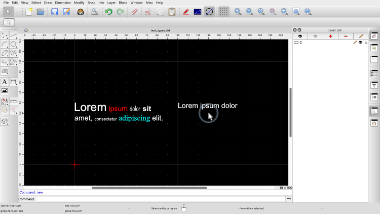
Simple texts can only have a single line in one uniform formatting.
Simple texts are easier to use with limited flexibility while multiline texts can be a bit harder to manage but offer more flexibility.
Example drawing: font_types.dxf

QCAD offers two different types of fonts: TrueType fonts and line fonts.

TrueType fonts are the fonts we know from other applications as shown here in the example at the top.
QCAD can use the TrueType fonts that are installed on the operating system level.

In addition, QCAD also offers a set of line fonts.
These fonts are defined using simple geometric shapes, typically lines, arcs and splines as shown here at the bottom.
Which fonts are used in a drawing is a matter of personal preference as well as industry or company specific standards.

If there are many system fonts installed, we can reduce the list of fonts available to QCAD in the application preferences.

Here, we can limit the list of fonts we want to use with QCAD to make the font selection more convenient.

To create a text entity we use the text tool of QCAD.

We first want to create a simple text, so we click the check box for simple texts.

We choose the desired font,

The text height is specified in drawing units.


We enter the text into the text area at the right.

We can now place the text in the drawing.


If we want to add multiple, similar texts, we can simply change the text in the options toolbar at the top without having to start over.
When we are done, we click the right mouse button to terminate the text tool.

Once a text has been created, we can edit its properties using the property editor which we have introduced in a previous tutorial.
Lets have a look at the vertical alignment property.

The text is currently vertically aligned to the top of the text.

This means that the text is displayed just below its reference point.

If we change the vertical alignment to the bottom of the text, the text touches the reference line with its bottom most part, here the bottom of the letter "P".

We can also align the text to its base which puts the reference point of the text on the base line where the text would be written on.


The horizontal alignment can be left, right or centered.

The property "X Scale" lets us compress or stretch the text without changing its height.

A value that is smaller than 1 indicates that the text is compressed horizontally.

A value greater than 1 stretches the text horizontally.

With a value of 1, the text is displayed at its original width.
Adjusting the X scale can be useful for fitting text into a specific area.

To create a multiline text, we use the same text tool as before.

This time, we uncheck the check box for simple texts.


We can still choose the desired font and text height.

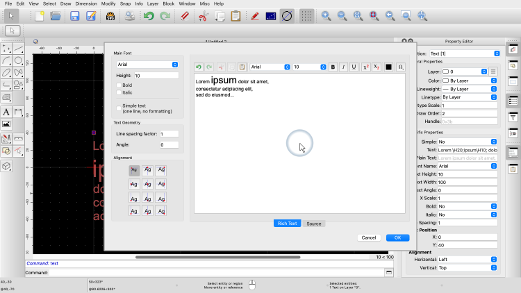
At the right, we enter our text.
But now, we can also use different fonts, text heights, colors and other attributes for any part of our text.

We can for example change the text height of a single word.


We can also have multiple lines in our text.

Among the properties of this text, we can find a property for the text width.


If this property is set to a value other than zero, the text is automatically wrapped at the given width if possible.
If we look at the Text property of our text entity, we can see that the property editor shows various codes with our text.
These codes instruct QCAD how to render the text, here with the change in height.

To edit a formatted text, it is usually more convenient to double-click it which brings up the text dialog.

The last thing we want to show in this tutorial is how to explode a text into geometric entities.


We first create a formatted text again.


We choose a more decorative font for this example.


We make the second part of the text italic.
We select the text to explode it.


To break up the text, we start the explode tool.

At first sight, this doesn't seem to change anything.
However, on closer inspection, we can see that there are now two separate text entities.


The formatted text has been exploded into two simple texts, each with uniform formatting.
To break up the texts further, we can explode these two texts again.

This breaks up the texts into polylines.


Exploding a third time, breaks up these polylines into individual line and arc entities.
Note that the original text entity no longer exists.
The text has been replaced with the contour of its outline as lines and arcs.
Exploding a text can be useful to edit the geometry of a decorative text for example to create a logo based on a text.
You should now know how to create, format and explode text entities in QCAD.
Be sure to practice this with your own installation.
Thank you for watching this QCAD tutorial.