First have a look at the new outer contour.
Where the quarter circles where typical 90 degrees they are now about 95 degrees or nearly 100 degrees.
You probably have trimmed them to the larger straight edges disregarding the short edges at those corners.
At the left high quarter circle the 2 slots are disregarded.
These 2.5mm wide slots can not be cut by the newly added profile with a 6mm cutter.
And hardly by the 2.5mm toolpath in the former art because a round cutter can not cut a sharp inside corner.
The minimal interior rounding radii are half the cutter size.

danny10 wrote: ↑Fri Jun 21, 2024 1:48 pm
Thanks, but i still don't see that the mill is going into the drilled hole, before milling ?
The drilling cycle is independent of your profile cycle.
QCAD will not automatically use the pre-drilled holes as entry positions.
In Andrews example the hole to drill is placed at the start of the Lead-In.
That is what I meant by "
Adapt drill position".
Normally a suited router bit can plunge straight down into the material at low FEED.
Although a gentle ramp down into the material is far better for this type of cutters and this can be done at optimal FEED.
Indeed, some end-mills are not capable of doing that an a pre-drilled hole is required.
Then the pre-drilled hole is typically at least somewhat larger than your end-mill.
You may ruin your cutting edges of your mill when it is a tight fit ...
... It is rubbing instead of cutting on the way down but that also depends largely on the type of stock material.
Partial solution:
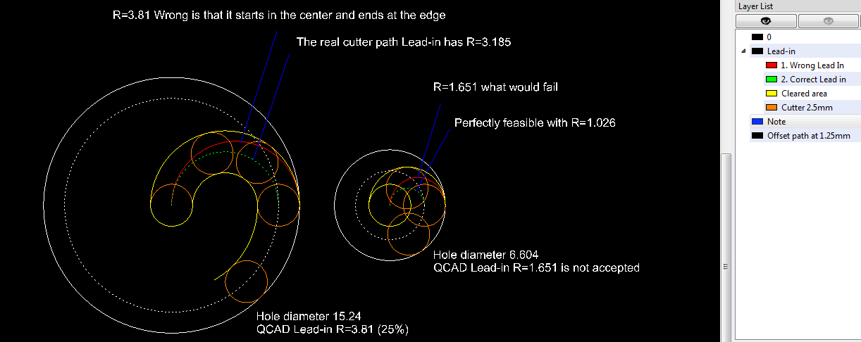
The only way I see that a Lead-in path can start at the center of the hole and end cutting tangentially at the outer edge is using a hole size related Lead-in that is a semi circle.
Under QCAD/CAM and for a hole of 15.24mm diameter that would be something as a semi circular Lead-in with R=3.81 (=25%
)
But for a hole of 6.604mm that would fail

...
... Simply because R=1.651mm and for some reason the entry radius must be larger than the tool (>2.5mm).
Below you can see that it is
perfectly feasible and that the radius of the entry path is not 1.651, in
green with R=1.026 it is even smaller.

In yellow I represented the cleared area by the cutter and that is fully unrelated to the
red Lead-in.
But perfectly related to the
green entry path.
- Also see attached dxf
- Lead-in from center.png (28.51 KiB) Viewed 60501 times
For me this is a misconception

There is something wrong with calculated offset paths ...
Seemingly the circular Lead-in is defined as the arc from center mill to the outer edge of the mill (In
red).
As if the cutter has no size to start with and ends with a certain radius.
As if the cutter size is gradually compensated from zero to R=2.5mm.
Mimicking G41/42 but a (
linear) cutter compensation can never be done in a circular motion.
The motion required going trough the virtual centers is not a simple arc and certainly not supported by all motion controllers that I know of.

- Practically impossible
- Circular cutter compensation.png (5.9 KiB) Viewed 60501 times
Related:
https://www.qcad.org/rsforum/viewtopic. ... 724#p44206
For a eighth circle I call it '
donkey ears' and you may discover that it won't be fixed.

- For a 15.24mm hole, 6.604mm not feasible
- Lead-in from center QCAD.png (7.17 KiB) Viewed 60378 times
You fooled the profile generation with a cutter = 2.499 and Lead-in Radius = 2.500

But that won't do the trick ....
And it is not the whole story because we are missing the cutter path starting at the Lead-in begin and something similar for the Lead-out.
The standard assumptions and Math for the offset are failing here.
The offset path should be a dot, simply plunge and back up with no motions in XY and disregarding a Lead-in/out or overcut.

- Hole diameter 2,5.png (9.52 KiB) Viewed 60501 times
A hole that is pre-drilled by a 2,5mm drill ... Does that require milling by a 2,5mm mill?
As said, the QCAD/CAM Lead-in radius must be tweaked according the hole size.
There is no one shoe that fits all.
Applicable for hole sizes of
over twice the Lead-in radius although it is feasible for 100,00..01%

At some point you may consider drawing the offset path and Lead-in (dotted) yourself as per example dxf and mill on path ...
Regards,
CVH