Example drawing:
Hammer.dxf Example image:
Hammer.png In this tutorial, we will learn how to insert
and align images in QCAD. In QCAD, we can add images to our
drawings. This is useful if we want to trace a scanned
plan, use a photo as a guide, or turn a hand-drawn sketch into a
CAD drawing. Sometimes, company logos or product photos are
also inserted into drawings as images. We begin this tutorial by inserting an image
into our drawing. When we say "image", we mean a bitmap such as
a photo. A bitmap is made of many tiny colored squares
called pixels, instead of the geometrical shapes like lines and
arcs that we usually see in CAD or vector drawings. In this example, we can see a bitmap of a
screw on the left side and a vector drawing of the same screw on
the right. Before we insert the image, we activate a
dedicated layer for our image, so we can easily show or hide the
image as desired. We use the bitmap tool in the CAD toolbar at
the left to insert an image. QCAD shows the file dialog to let us choose an
image file to insert. We can choose for example a JPEG file, a PNG
file or one of many other bitmap formats that are supported by
QCAD. Note that images are not stored inside a CAD
drawing. The drawing uses the image file on the disk drive in order
to display it. This means that we have to keep the image file
on the disk even after inserting the image. To make sure that QCAD can always find all the
images that belong to a drawing file, we keep the drawing file and
all referenced image files in the same project folder. For this example, we have created a project
folder called "Hammer". This project folder contains the drawing file
"Hammer.dxf". Our project folder also contains the image
file which we are about to insert: "Hammer.png". We select this PNG file, since this is the
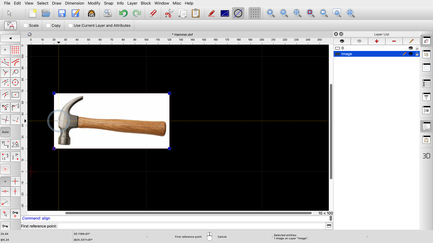
image file we want to insert. We can now place the image in our drawing
using the left bottom corner as reference point. In the options toolbar, we can see and adjust
the image size in drawing units. A bitmap has no particular size. Its size in
our CAD drawing depends on how the pixels of the image are
scaled. A single pixel of the image might for example
be ten drawing units in size or only one tenth of a drawing
unit. By default, the image is inserted with its
pixel size in drawing units, so that one pixel measures one drawing
unit. The width of this image is 1407 pixels, as
shown in the options toolbar. Right now, this would translate to 1407
drawing units. If we know the exact size our image should
have in the drawing, we can enter the desired size in drawing units
here. For example if we insert an image from a
scanner with the exact size of an A4 page, we can enter the size of
an A4 paper here. For this example, we do not know the exact
size our image is supposed to have. We scale it down a bit for now, just to make
sure it fits on our visible drawing area. Note that this does not in any way affect the
image file on our disk. The image is only displayed smaller now in our
drawing area with a width of exactly 100 drawing units. We place the image into our drawing with a
left click. We will later scale the image to the exact
desired size using a more appropriate approach. The image we have just inserted shows a
photograph of a hammer on a white background. The original photo might already have been
prepared with an image editor. For example to change the background
to white. The exact steps required to prepare a bitmap
in such a way depend on the image editor used and are beyond the
scope of this tutorial. The inserted image is currently not to scale
and the handle of the hammer is also not quite horizontal. This is typical for bitmaps that were created
from photos or scans. In the following steps, we will scale and
rotate the image into place so that the hammer handle is horizontal
and the hammer has the desired size. First, we select the image that we want to
align. The tool we need is located in the
modification tools menu of QCAD. Here we can find the tool to align a selection
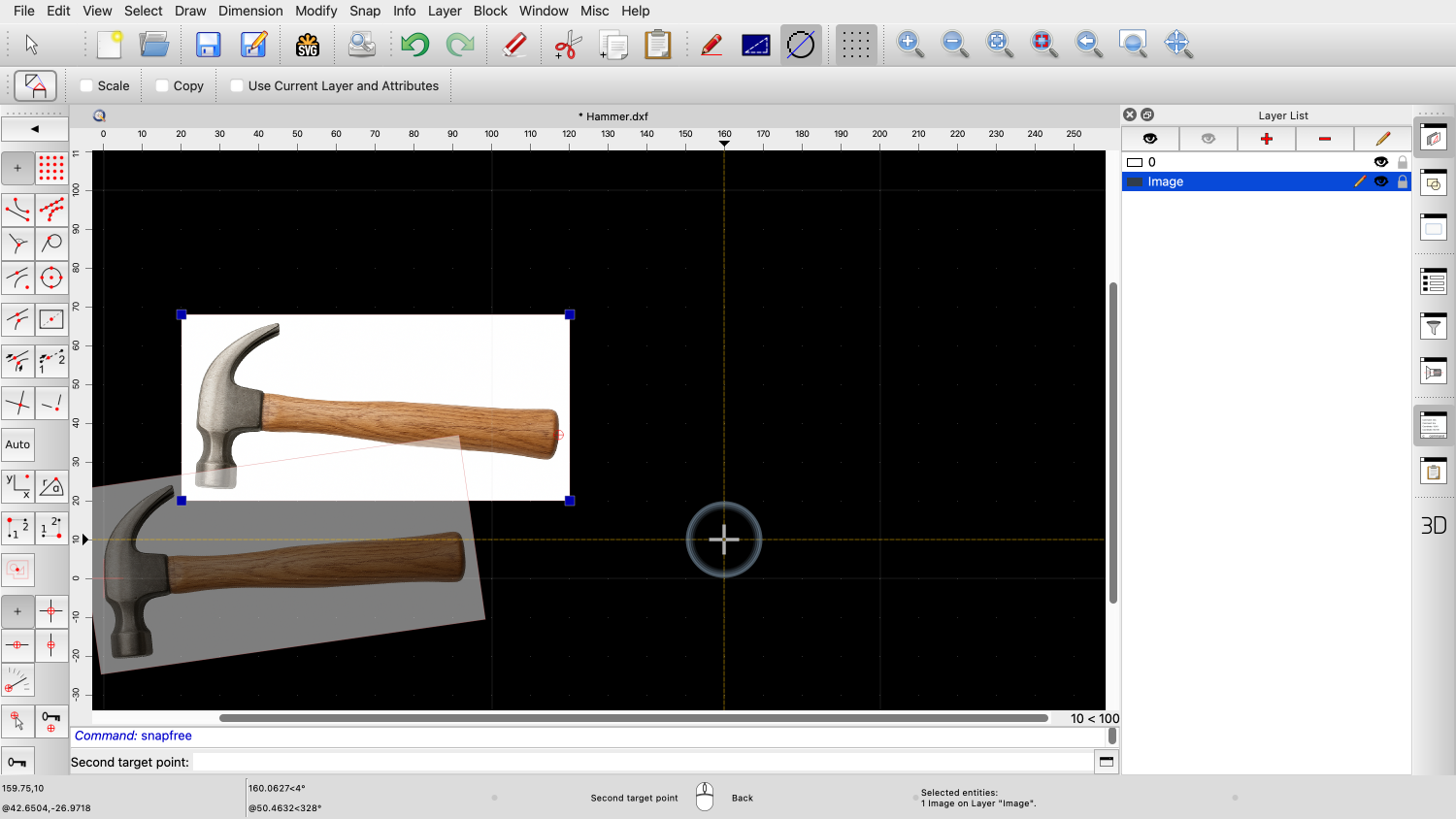
based on given reference points. This tool rotates and scales the current
selection in such a way that two given reference points within the
selection are moved to two new target points as indicated by the
red arrows. In this example, we want the top of the hammer
to be moved to the zero point. The bottom end of the hammer should be moved
to a position to the right, so that the hammer is horizontal and
has the desired length. The tool prompts us for the first reference
point. We choose a reference point in our image that
we can easily identify and place at a defined location in our
drawing. The first reference point is usually the start
point of a known distance in the image. In this example, we choose the top point of
the hammer head. We cannot snap to the pixels of an image, so
we use the free snap tool to set the reference point. We zoom in to position the reference point as
accurately as possible at the desired position of the image. This will never be 100% precise due to the
nature of bitmaps which are generally not 100% precise or
sharp. Next, we set the target point for the chosen
reference point. The chosen reference point will be moved to
this target point. We click the zero point for this example. For the second reference point, we click the
middle of the handle end. QCAD now shows a preview of how the image will
be transformed, depending on the position of the second target
point. Scaling is optional for this tool, so we have
to make sure that the scale option is checked since we do want to
scale as well as rotate the image. The second reference point is moved to the
target point we choose. The image is rotated and scaled in such a
way that the chosen reference points now line up with the chosen
target points. We know from measuring the real hammer that
the hammer is 250 Millimeters long, so we set the target point 250
units beside the previous target point. The image is scaled and rotated so that the
first reference point lies at the zero point and the second
reference point is 250 Millimeters to the right. The image has been adjusted to the desired
angle and size and is now at a scale of 1:1. This can, for example, serve as a basis for
image tracing or vectorization, which we will cover in the next
tutorial. You should now know how to insert images and
how to align them as desired. Be sure to practice this with your own
installation. Thank you for watching this QCAD tutorial.Video Transcript


